
Precifarm
Electric mobility infrastructure for Africa
PF-ENG-SOLAR-HUB-001 · v1.1
Engineering package
Solar Chargers & Charging Stations
Design basis and engineering task sheet for Precifarm route hubs, campus stations and private house hybrid charging.
1. Purpose
This package is the engineering design basis and single-site delivery task sheet for Precifarm solar-assisted DC charging stations.
| Type | Role | Typical user |
|---|---|---|
| Route charging hub | Reserved CCS2 windows for scheduled electric buses on Nairobi–Kisumu | Partner operator + Precifarm ops |
| Private campus / in-house | Multi-pedestal AC/DC on private land | Host organisation |
| Private house hybrid | Charger on the customer meter; optional rooftop solar + storage | Homeowner / estate |
Governing design principles
- Type 2 public AC · CCS2 public DC. CHAdeMO / GB/T only for defined fleets.
- Contracted bus demand before speculative public capacity.
- Modular shared-power cabinets; expand against measured utilisation.
- Electrical safety and the site import limit stay local (edge clips cloud commands).
- OCPP 2.0.1 greenfield baseline; OCPP 2.1 / ISO 15118-20 upgrade path.
- KPIs: first-attempt charge success and delivered kWh — not heartbeat-only uptime.
- Kenya Power connection study before land or charger commitments.
2. System concept
Dispatch order at the edge (cloud is advisory):
- Electrical safety, emergency stop, insulation and thermal interlocks
- Declared site import limit (utility + transformer + switchboard)
- Reserved bus windows (timetable energy before public or opportunistic load)
- Tariff / demand-charge reduction
- Solar self-consumption and BESS state-of-charge floors
| Layer | Function |
|---|---|
| Energy supply | Grid import + canopy/rooftop PV + optional LiFePO₄ storage |
| Fast charging | Modular CCS2 DC (120–180 kW town/bus · 240–320 kW highway class) |
| Civil / canopy | Weather protection, PV mounting, bus approach, queue, dwell |
| Operations | OCPP 2.0.1 sessions, metering, reserved windows, remote monitoring |
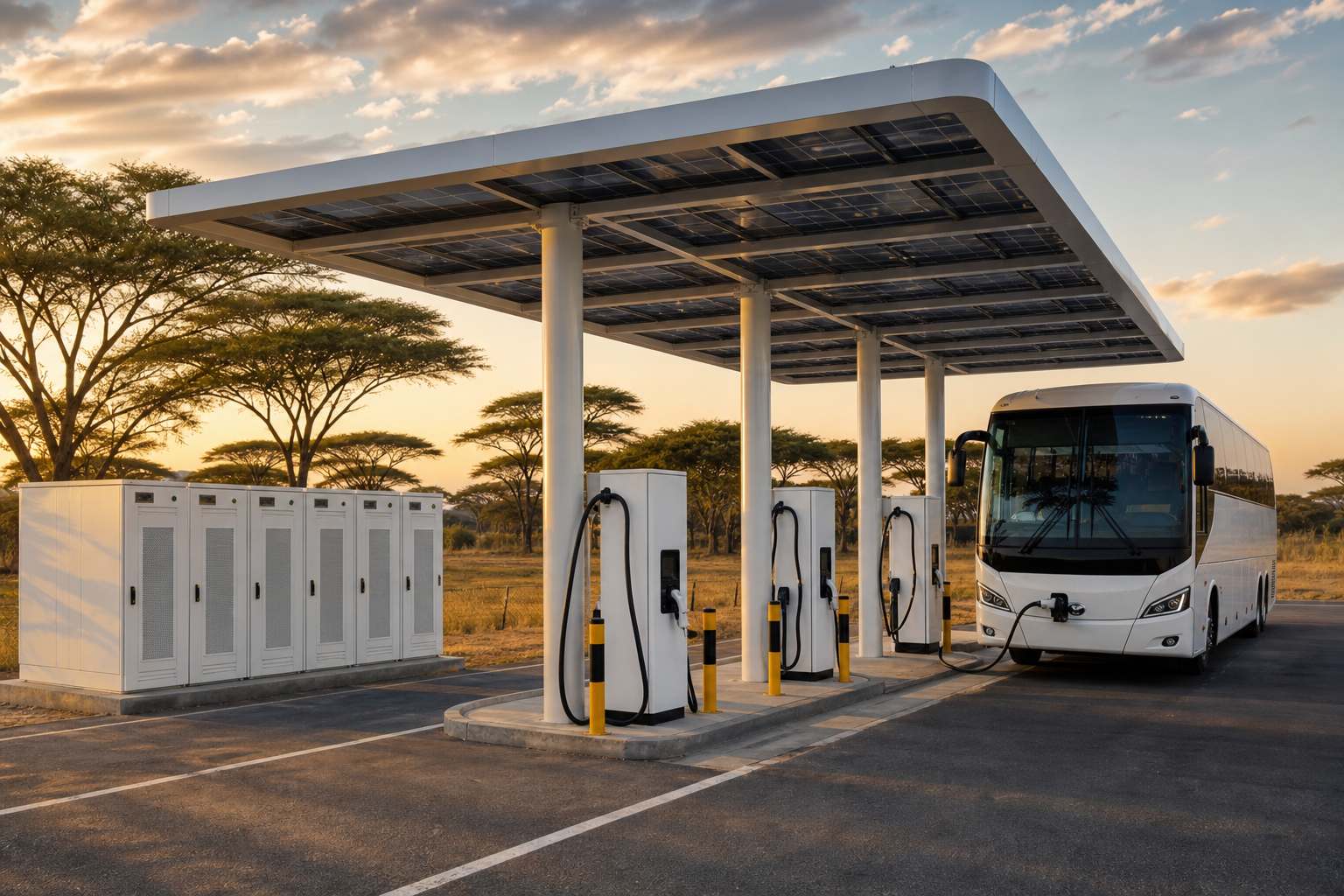
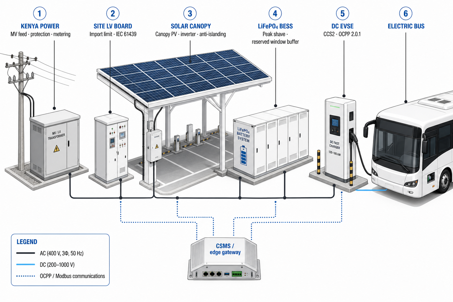
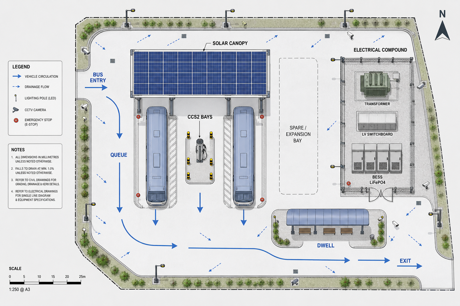
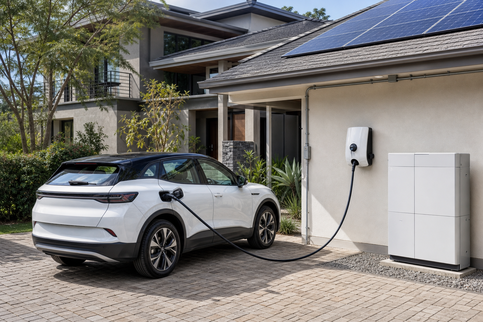
2.1 Photo annex — stations, sites and vehicles
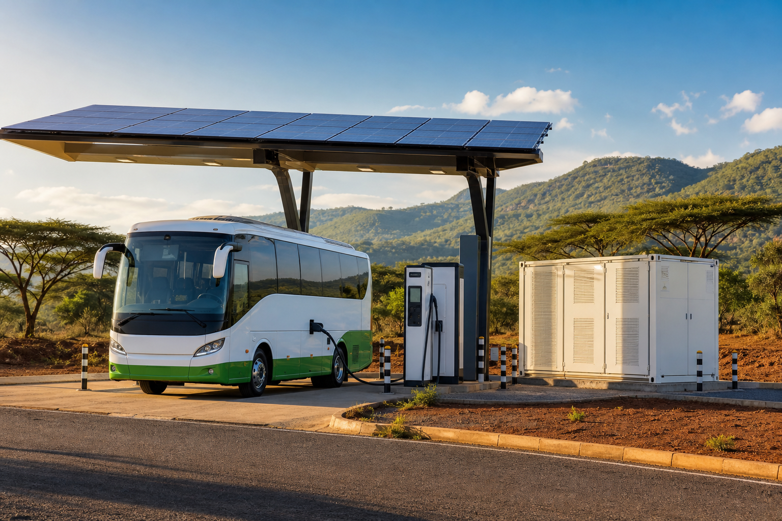
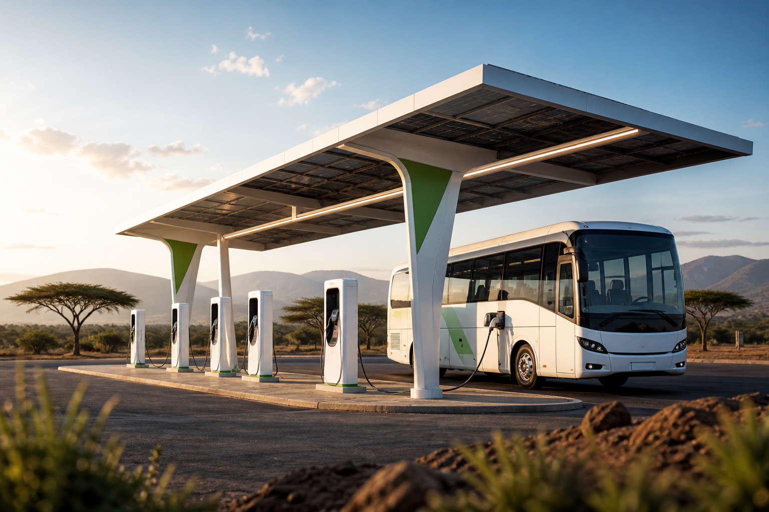
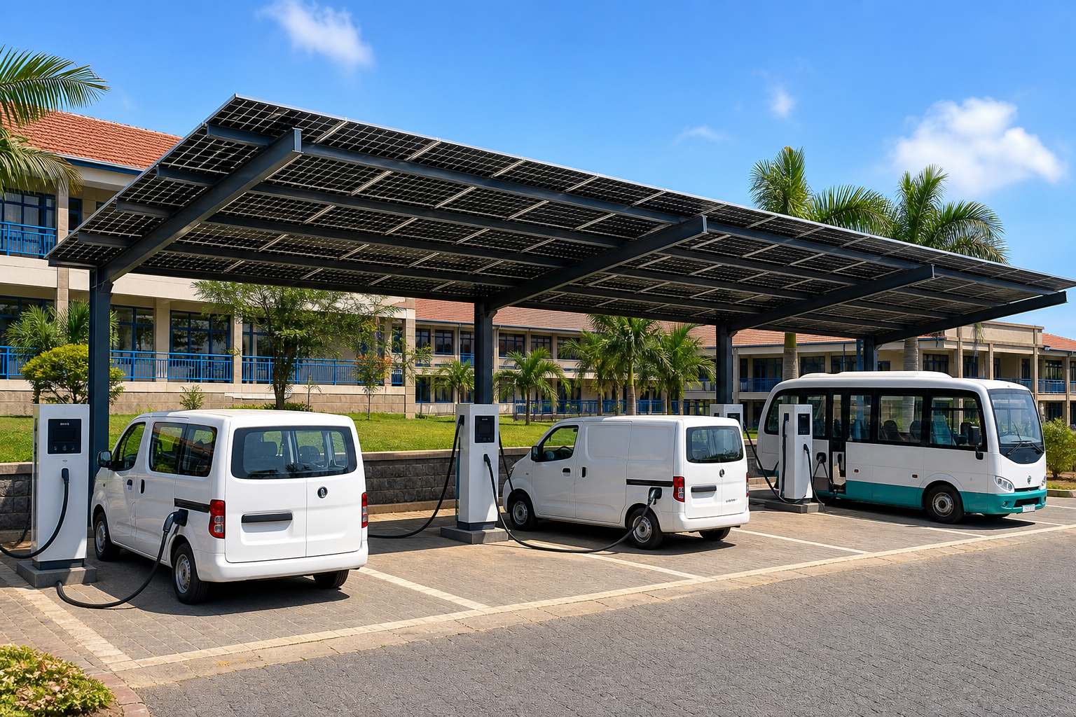
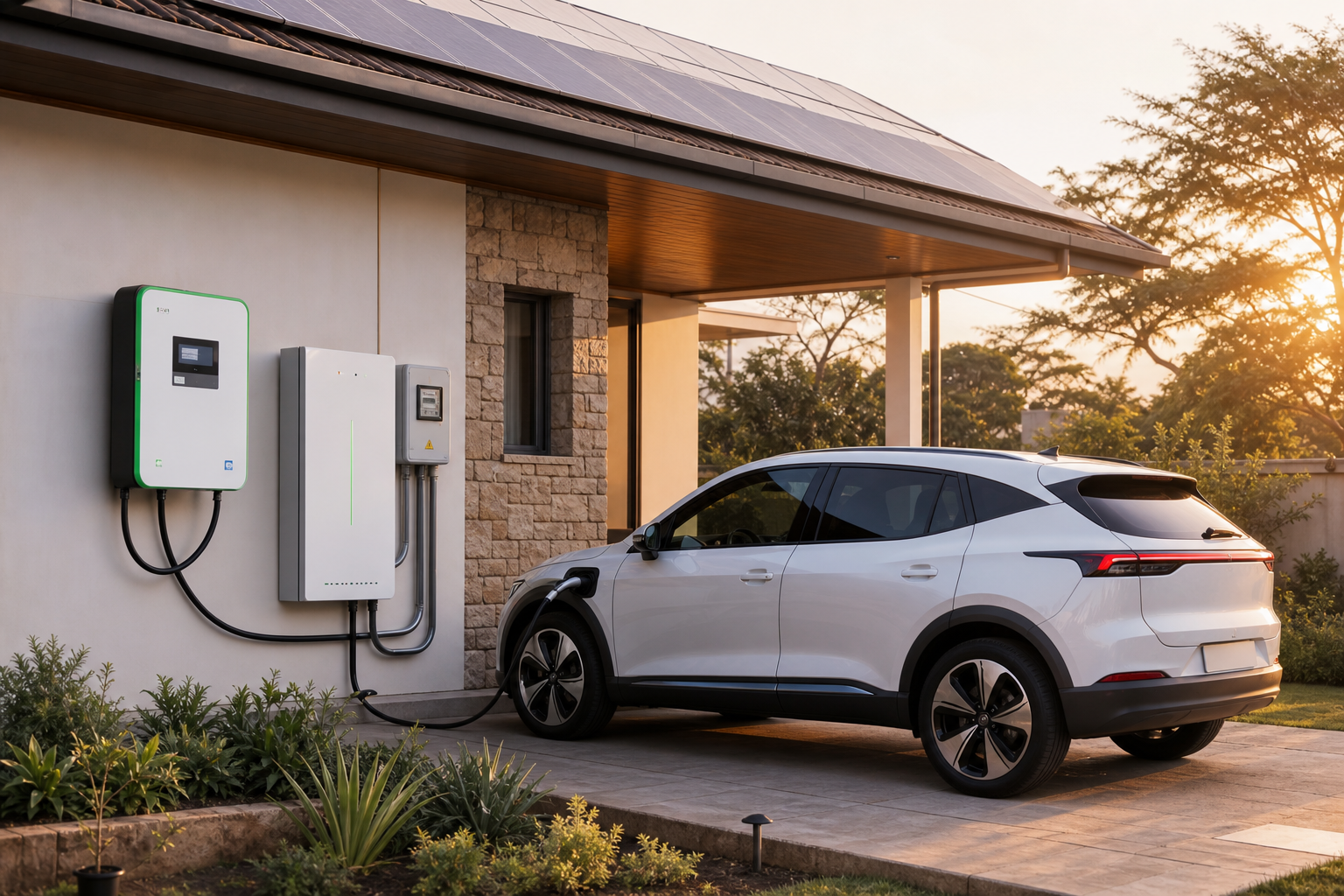
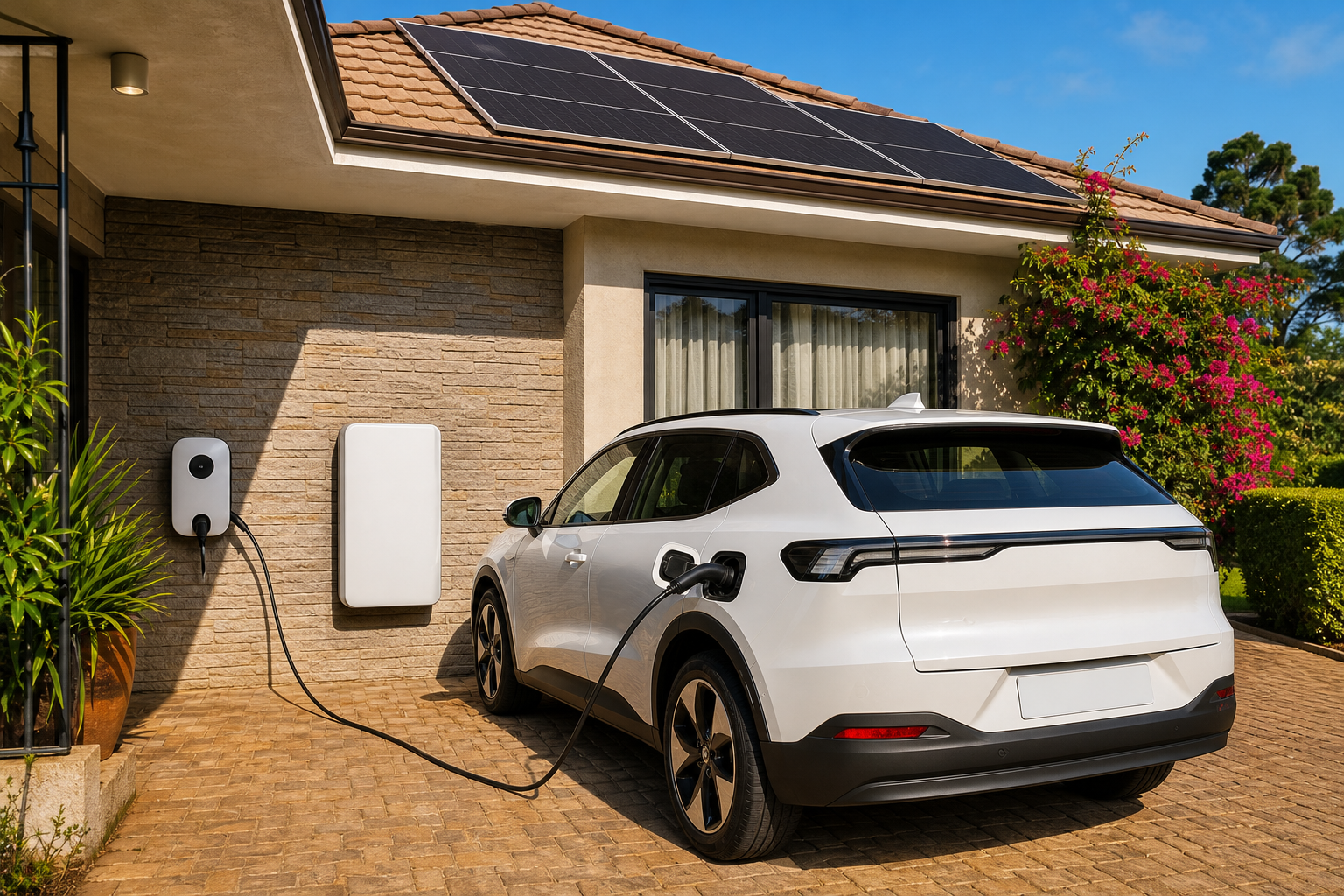
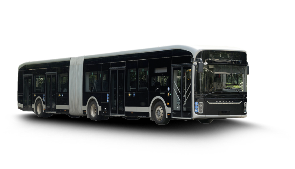
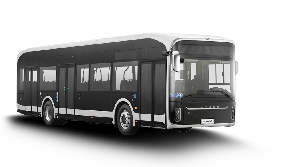
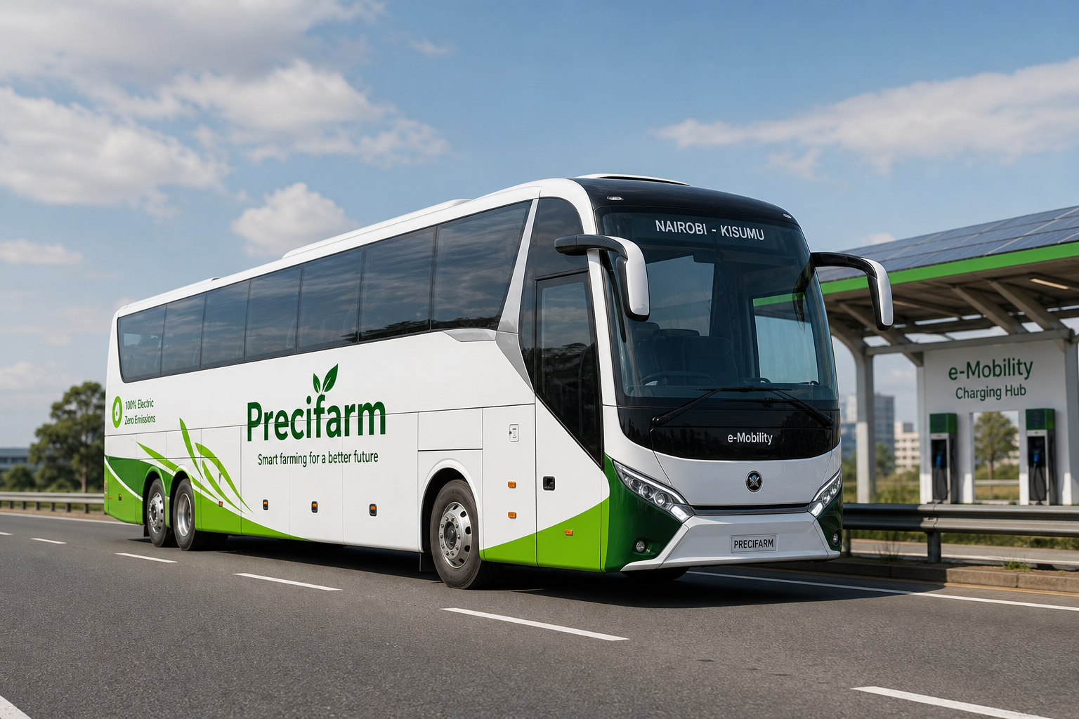
Additional reference imagery used across Precifarm charging surfaces. Illustrative — not as-built photography.
3. Design basis — route charging hub
3.1 Functional requirements
| ID | Requirement |
|---|---|
| R-01 | Deliver reserved CCS2 DC energy so scheduled electric buses leave on timetable |
| R-02 | Prefer Type 2 (AC) / CCS2 (DC) as Kenya public defaults |
| R-03 | Modular shared-power cabinets; expand only against contracted demand |
| R-04 | Integrate solar canopy where irradiance and structure allow |
| R-05 | LiFePO₄ storage for peak shaving / weak-grid resilience (site-dependent) |
| R-06 | OCPP 2.0.1 to CSMS; durable edge queue for offline recovery |
| R-07 | First-attempt charge success and delivered kWh as primary KPIs |
| R-08 | At least two operational DC ports at a corridor hub so one fault does not strand the route |
| R-09 | Hard site-import clip from local metering — cloud setpoints cannot exceed the utility envelope |
| R-10 | Identify the coach, start the reserved session, and write a metered session record for settlement |
3.2 Nairobi–Kisumu site classes (planning)
Route one is Nairobi–Kisumu (~345 km, ~4 h 45 m). Hubs exist to protect the timetable.
| Site class | Planning role | Typical dwell | Equipment class |
|---|---|---|---|
| Nairobi depot / terminus | Overnight and pre-departure top-up | Hours (managed) | 120–180 kW DC + 11–22 kW AC |
| En-route (e.g. Nakuru) | Opportunity charge if remaining range is insufficient | 20–40 min | 120–180 kW; 240–320 kW if dwell is shorter |
| Kisumu terminus | Arrival recovery + next-day readiness | Hours / overnight | 120–180 kW DC + AC as dwell allows |
3.3 Energy model (planning assumption)
| Parameter | Planning value | Note |
|---|---|---|
| Specific consumption | 1.2 kWh/km loaded | Replace with OEM / loaded test |
| Route distance | ~345 km | Nairobi–Kisumu |
| Trip energy | ~414 kWh | 1.2 × 345 |
| Beachhead departures | 5/day | Canon planning assumption |
| Mid-route opportunity charge | 80–150 kWh | 20–40 min at 150–180 kW usable |
Worked example — one reserved window (illustrative): 120 kWh in 30 min → 240 kW at the vehicle. At 95% charger efficiency, AC input ≈ 253 kW. If the Kenya Power import limit is 180 kW, BESS must cover the gap: (253 − 180) × 0.5 ≈ 37 kWh plus reserve → usable BESS typically ≥ 80–100 kWh for that window.
A 40–80 kWp canopy in Kenya yields roughly 180–440 kWh/day. Against a 1,500 kWh/day hub, PV covers on the order of 12–30% of daily energy. Use it for cost, shade and resilience — not as a substitute for the feeder.
3.4 Typical equipment class (planning)
| Element | Planning class | Notes |
|---|---|---|
| DC dispenser | 120–180 kW (town/bus) · 240–320 kW (highway) | RFQ against Chinese charger shortlist |
| Architecture | Modular shared-power preferred | Add cabinets against utilisation |
| Connector | CCS2 dual-port at corridor hubs | CHAdeMO/GB/T only if fleet-specific |
| PV canopy | 40–80 kWp typical two-bay | Export only with written utility approval |
| BESS | LiFePO₄, 100–250 kWh usable first site | Dispatch under import limit; fire separation |
| Transformer | Concept 315–500 kVA after diversity | Site study required |
| Communications | Dual path at critical hubs | Ethernet + cellular |
3.5 Solar canopy sizing method
- Structure first — canopy area is set by bus geometry, wind and seismic.
- Module packing — planning ~160–200 Wp per m² of canopy plan area.
- Yield — Kenya planning 4.5–5.5 kWh/kWp/day (site PVsyst later).
- Self-consume into BESS and site load; export only if the connection offer allows it.
- Anti-islanding — inverter/PCS trip on loss of mains.
Illustrative two-bay canopy: 12 m × 24 m ≈ 288 m² → ~50 kWp → ~225–275 kWh/day.
3.6 BESS sizing method
Size storage to the binding constraint, then take the larger of: reserved-window gap, peak-shave to an affordable kVA, ride-through for one abort/restart, and SoC floors for the next contracted window. Chemistry: LiFePO₄ outdoor cabinets.
3.7 Electrical design checklist
| ☐ | Item |
|---|---|
| ☐ | Kenya Power connection study and declared POC voltage (LV or MV) |
| ☐ | 15-minute load profile: reserved windows, public, auxiliaries, PV, BESS |
| ☐ | Transformer / switchboard sizing (IEC 61439 / 60947) |
| ☐ | Cable ampacity, voltage drop, fault withstand |
| ☐ | Protection coordination; Type B RCD / RDC-DD as required |
| ☐ | Earthing, bonding, touch/step voltage |
| ☐ | Lightning risk (IEC 62305) and coordinated SPDs |
| ☐ | Harmonics, PF, flicker; PV/BESS anti-islanding and export approval |
| ☐ | Thermal management for high-power DC cabinets |
| ☐ | Emergency stop, isolation, and responder access independent of software |
3.8 Civil & site checklist
| ☐ | Item |
|---|---|
| ☐ | Safe entry/exit and queue storage for 12 m-class buses (drive-through preferred) |
| ☐ | Dispenser clearances, impact protection, cable management |
| ☐ | Canopy wind/seismic loads; PV mounting integrity |
| ☐ | Separated transformer, switchgear, charger and BESS compounds |
| ☐ | Drainage away from energized equipment; lighting, CCTV, fire access |
| ☐ | Passenger dwell offset from the electrical compound |
| ☐ | Spare ducts, foundations and switchboard ways for one expansion bay |
4. Design basis — private campus / in-house station
| ID | Requirement |
|---|---|
| C-01 | Start from vehicle count, arrival SOC and dwell — not from a brochure kW |
| C-02 | Prefer 11–22 kW Type 2 AC where vehicles park for hours; add DC only for short dwell |
| C-03 | Building / estate import limit and landlord earthing govern charger count |
| C-04 | Submetering for the host; OCPP if revenue-bearing or fleet-managed |
| C-05 | Optional canopy PV + LiFePO₄ using the same sizing methods as route hubs |
| C-06 | Fire access, impact protection and isolation — campus does not mean light duty |
5. Design basis — private house hybrid
| ID | Requirement |
|---|---|
| H-01 | Charger on customer property and meter — not a public hub |
| H-02 | Start from duty cycle: typically 7.4 kW AC; DC only when justified |
| H-03 | Optional solar + storage for overnight resilience |
| H-04 | Same engineering discipline: survey, install, commissioning, support |
| H-05 | App visibility for personal home charging when product supports it |
| H-06 | Type A 30 mA plus 6 mA RDC-DD, or Type B, on a dedicated final circuit |
6. Software & cybersecurity (station)
| Topic | Baseline |
|---|---|
| Charger protocol | OCPP 2.0.1 (greenfield) |
| Upgrade path | OCPP 2.1 / ISO 15118-20 |
| Edge | Offline auth snapshot, durable session queue, local load management |
| Cloud | Sessions, billing hooks, fleet windows, OTA, fault management |
| Security | Segmented OT/IT, least privilege, signed firmware |
| Safety | Software cannot override hardware E-stop, insulation monitoring, or import-limit trip |
7. Kenya approvals and hold points
Hold capital and equipment orders until these are in the site pack (or explicitly waived in writing).
| Gate | Owner | Evidence |
|---|---|---|
| Contracted demand | Commercial | Operator window / kWh commitment |
| Site control | Commercial + legal | Host agreement, tenure, access |
| Kenya Power enquiry | Electrical | Feasibility / connection offer, tariff, export rules |
| Licensed design | EBK-registered engineer | SLD, protection, earthing |
| EPRA / Energy Act | PM | Charging-infrastructure guideline checklist |
| NEMA / EIA | HSE | Screening decision or licence as triggered |
| County / fire | Civil + HSE | Building, fire, BESS separation |
| KEBS / IEC equipment | Procurement | Certificates matching the shipped SKU |
| Commissioning | Field + software | Acceptance tests signed |
8. Engineering task sheet
Delivery tracker for a single site. Checkboxes are hold points.
Phase A — Feasibility
| ☐ | ID | Task | Owner | Output |
|---|---|---|---|---|
| ☐ | A-01 | Confirm contracted demand / duty cycle | Commercial + Eng | Demand note |
| ☐ | A-02 | Site walkover, photos, access, host constraints | Field eng | Site pack |
| ☐ | A-03 | Grid enquiry / connection study request | Electrical | Utility letter |
| ☐ | A-04 | Concept single-line diagram | Electrical | SLD v0 |
| ☐ | A-05 | Concept layout (canopy, pedestals, storage, circulation) | Civil + Eng | Layout v0 |
| ☐ | A-06 | Capex/opex planning estimate | Eng + Finance | Cost sheet |
| ☐ | A-07 | Capital gate: demand + site control + feeder path | PM | Go / no-go |
Phase B — Design
| ☐ | ID | Task | Owner | Output |
|---|---|---|---|---|
| ☐ | B-01 | Detailed SLD and protection schedule | Licensed electrical | IFC pack |
| ☐ | B-02 | Cable schedule and earthing design | Electrical | Schedules |
| ☐ | B-03 | Canopy / PV structural design | Structural | Calcs + drawings |
| ☐ | B-04 | BESS integration and fire separation | Electrical + HSE | Spec |
| ☐ | B-05 | CSMS / OCPP configuration sheet | Software | Config pack |
| ☐ | B-06 | Civil drainage, lighting, CCTV | Civil | Drawings |
| ☐ | B-07 | Statutory submissions | PM | Approvals log |
Phase C — Procurement
| ☐ | ID | Task | Owner | Output |
|---|---|---|---|---|
| ☐ | C-01 | RFQ against shortlist (bus/highway or house class) | Procurement | Vendor bids |
| ☐ | C-02 | Factory acceptance criteria + OCPP live test | Eng + Software | FAT checklist |
| ☐ | C-03 | Spares, warranty, local labour, ten-year parts | Procurement | Contract |
| ☐ | C-04 | Confirm Kenya SKU: CCS2, 50 Hz, OCPP 2.0.1, environmental rating | Eng | Conformity matrix |
Phase D — Construction & commission
| ☐ | ID | Task | Owner | Output |
|---|---|---|---|---|
| ☐ | D-01 | Civil and canopy install | Contractor | As-built |
| ☐ | D-02 | Electrical install and torque records | Contractor | QA pack |
| ☐ | D-03 | Charger / BESS / PV commissioning | Field eng | Commission report |
| ☐ | D-04 | OCPP end-to-end session test | Software + Field | Test log |
| ☐ | D-05 | Peak-load test against declared import limit | Electrical | Test sheet |
| ☐ | D-06 | Safety sign-off and handover | PM + HSE | Handover certificate |
| ☐ | D-07 | Operator training (T1–T3 as applicable) | Training | Attendance |
Phase E — Operate
| ☐ | ID | Task | Owner | Output |
|---|---|---|---|---|
| ☐ | E-01 | Reserved window calendar live | Ops | Schedule |
| ☐ | E-02 | Uptime and delivered-kWh dashboard | Ops | KPI weekly |
| ☐ | E-03 | Preventive maintenance plan | Field | PM calendar |
| ☐ | E-04 | Incident / exception process | Ops | Runbook |
| ☐ | E-05 | Utilisation review before next cabinet / port | Eng + Finance | Expansion note |
9. Acceptance criteria (route hub)
A site is engineering-accepted when:
- Documented connection agreement and site import limit are respected under peak test load
- At least one successful CCS2 session delivers metered energy to a representative vehicle
- A reserved-window rehearsal completes the contracted kWh inside the timetable (or a documented exception path is proven)
- OCPP session and meter values reconcile in CSMS
- Emergency stop, isolation, and earthing verification are signed
- PV anti-islanding and BESS fire/separation checks are signed where those systems are installed
- As-built SLD and O&M pack are filed
Engineering acceptance is necessary; it is not traction. Commercial live-route proof remains a separate Canon proof gate.
10. Related references
- Precifarm Master EV Charging Engineering Handbook
- Kenya Deployment Plan 2026–2040
- Chinese Ready-Made EV Charger Shortlist
- Software, Communications and Cybersecurity Architecture
- Canon — Reserved Route Charging product boundaries